We are leading Vibrating Motors, manufacturers, suppliers and exporters located in Ambrnath MIDC Dist Thane, maharshtra india.
Unbalance Vibrator Motors
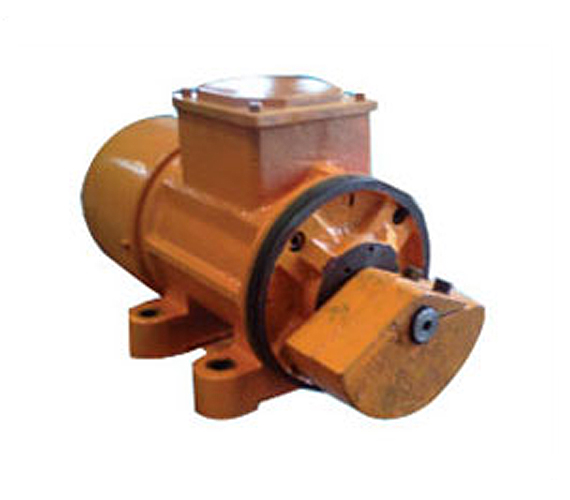
Vibrator motors are robust, highly stable under load, having cylindrical roller Bearings Vibration resistant, high quality resin impregnated windings. End Shield fitted with rubber 0 rings to give dust tight and watertight enclosure. Quite running and require no maintenance.
Robust terminal board, cable wire cast in vibration resistant synthetic resin. Reliable high torque starting, Absolutely secure fixing of our of balance weights only the inner weights are adjustable, with legible markings on the weights.
Vibratory Motors
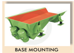
Mitool Vibratory Motors used in Vibro feeders are totally enclosed 3 phase, squirrel cage induction motors with adjustable, eccentric weights mounted on the extended shaft to set up vibrations during rotation. The design of shaft and the selection of bearing has been carefully done to withstand heavy radial loads. Two identical motors mounted parallel to each other on a right and left, which is free to move in clockwise or anticlockwise directions, will produce linear vibrations. Both motors must rotate in opposite direction to each other. This principle is adopted for handling large bulky material in large feeders.
Technical Data & Dimensions
| Centrifugal force range | from 40to 35000 N. |
|---|---|
| Working moment | from 1 to 631 kgcm. |
| Suitable for Vibrator units with useful weight range | from 1 to 1440 kgs |
| PowerSupply | 415 Volts, 3 phase, 50 hz. |
| Rated output | 0.1 to 2.3 kw |
| Ambienttemperature | upto 60°C |
| Type of enclosure | IP55 |
| Insulation Class | 'F' Class |
Application
Vibrating Conveyors, Vibrating Screens, Conveyors Troughs and Tubes, Fields of Application: Coal, Lignite, Salt, Synthetic, Rubber, Fertilizers & Chemicals.
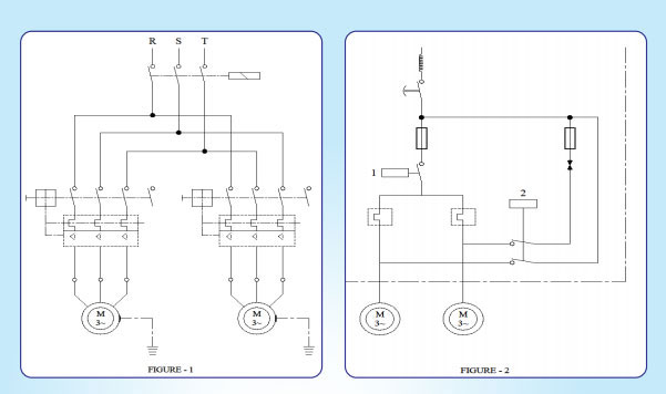
Vibration motors are connected to a three-phase system with flexible copper conductor cable. Connection can be effected as per (fig. 1) in the simplest manner by means of a common contactor, which must be interlocked by means of auxiliary contacts. We strongly recommend use of a circuit breakerwherevertwo motors are used.
On the other hand, with the latter connection, considerable oscillation occur, on the disconnection of the equipments, due to the fact that resonant frequencies of the support springs will have a comparatively slow run trough, especially at a time when the trough is empty and the bulk material is absent. Forthis reason, a connection ofthe motors via a break unit, (Fig, 2) with which the motors can be brought to a standstill through d.c. breaking in a period of one to two seconds, is recommendable.